Overview
This post is the seventh in a series that plans to document my progress through installing and configuring a small OpenStack Lab.
For other posts in this series, see the overview section of the introduction post.
In the last post, we covered some basic configuration of interfaces on a Cumulus switch.
This post will cover the last of our configuration required on our Cumulus switches - routing.
Configuration
First, I think it might be a good idea to recap what we want to be accomplished in terms of routing. Let’s take a look back to our production network diagram.
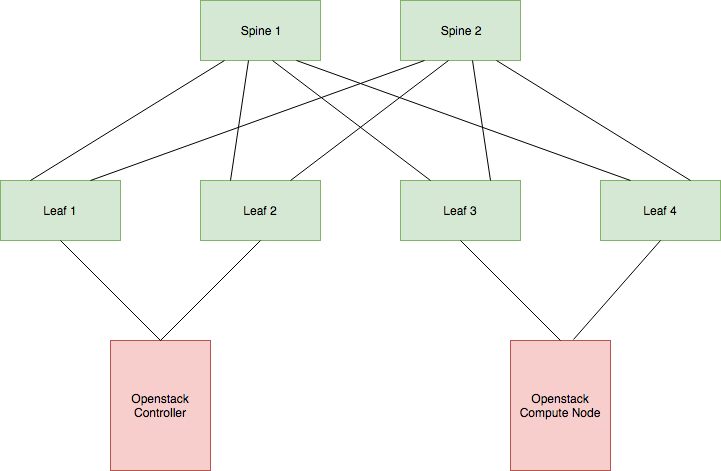
Our end goal with this topology is to have our OpenStack virtual machines able to talk to each other, even if they’re on the same subnet.
This can be accomplished by telling OpenStack to tag traffic with VLANs when it communicates across the network, which can work on a small scale quite well, but comes with the downsides of using VLANs as well such as requiring Spanning Tree be run to prevent loops from forming. It’s also not what I set out to learn about.
The other option is to tell OpenStack to use VXLANs to communicate over the network (Unfortunately at this stage OpenStack doesn’t yet support GENEVE as an option).
I won’t dive into the technical details of VXLAN in this post. Just know that VXLAN VTEPs (Virtual Tunnel Endpoints - The OpenStack hosts on our environment) send traffic by encapsulating received frames and tunnelling this across a layer 3 network to remote VTEPs. VTEPs need a way to learn what VNIs (Virtual Network Identifiers - VXLANs segment identifier, similar to a VLAN) are present in the network and on what hosts they reside on. They also need a mechanism to learn where MAC addresses within each VNI exist (What VTEP they terminate to).
VXLAN does have a native learning capability built in that uses multicast, but this has its shortcomings (like needing to run multicast in your network). That’s where EVPN comes in.
EVPN can act as a control plane for VXLAN and does so by advertising VXLAN information over BGP.
Okay, we have some requirements:
- Have IP reachability across our network so that VXLAN can tunnel traffic.
- Support the OpenStack nodes in advertising VXLAN information over BGP using EVPN.
I’ve decided to deploy OSPF as an underlay routing protocol. This will advertise loopback addresses between all hosts (switches and OpenStack nodes) for IP reachability.
Loopback reachability is also required for BGP, which we’ll be deploying on the spine switches in addition to the OpenStack nodes.
While the spine switches won’t be participating in the VXLAN network (they won’t have any VNI’s or MAC addresses to advertise), they will be acting as route reflectors.
The deployment of route reflectors isn’t needed in an environment this small but quickly becomes important in a larger network.
For further reading on other EVPN+BGP network designs, I would recommend taking a look at this post over on ipspace.net
That’s it for the design. Let’s jump into the configuration.
Ansible Playbook/Role
We’ve already created the playbook in a previous post, which references the “cumulus-base” and “cumulus-interface” roles. I’ll create a new one named “cumulus-routing”.
$ mkdir -p /etc/ansible/roles/cumulus-routing/tasks/
And add this to our playbook - “openstack-cumulus.yml”:
---
- name: Configuring Cumulus switches
  hosts: openstack_cumulus
  become: true
  gather_facts: true
  roles:
    - role: cumulus-base
      tags:
        - cumulus-base
    - role: cumulus-interface
      tags:
        - cumulus-interface
    - role: cumulus-routing
      tags:
        - cumulus-routing
Onto our role.
Free Range Routing
Free Range Routing (sometimes referred to as FRRouting or simply FRR) is an open source routing suite that Cumulus deploys on their switches. FRR manages the operations of any routing processes running on the switch, including OSPF and BGP.
FRR has a few main configuration files, stored under the directory “/etc/frr”:
$ ls -alh /etc/frr/
total 16K
drwxrwxr-x 1 frr  frr      74 Dec  8 13:52 .
drwxr-xr-x 1 root root   3.5K Dec  8 13:46 ..
-rw-r--r-- 1 frr  frr    1016 Nov  8 11:28 daemons
-rw-r--r-- 1 frr  frr    1.2K Nov  8 11:28 daemons.conf
-rw-r--r-- 1 frr  frr     120 Nov  8 11:28 frr.conf
-rw-r--r-- 1 frr  frrvty   60 Nov 14 07:30 vtysh.conf
Let’s quickly go over what each is used for:
| File | Purpose |
|---|---|
| daemons | Controls what daemons (routing processes) are run. All daemons are disabled by default. |
| daemons.conf | Controls the options passed to daemons when they start (If they’re enabled in the above file). |
| frr.conf | Controls the configuration of all daemons. The meat of the routing configuration. |
| vtysh.conf | Controls how the command line interface utility (vtysh) operates. |
In the context of the configuration we’re writing in this role, the files “daemons.conf” and “vtysh.conf” can be left alone.
That leaves us with needing to change the “daemons” and “frr.conf” files, which we’re going to do with the Ansible template module. Our “tasks/”main.yml” file ends up looking like the below for this role:
---
- name: Configure FRR (Free Range Routing)
  template:
    src: "{{ item }}.j2"
    dest: "{{ cumulus_frr_config_dir }}{{ item }}"
  loop:
    - daemons
    - frr.conf
  notify: Reload FRR

- name: Start and Enable FRR
  service:
    name: "{{ cumulus_frr_service_name }}"
    state: started
    enabled: yes
Note how we’ve only got two tasks:
- Configure Free Range Routing.
- Ensure that the FRR service is started (Because this is disabled by default).
We’ve also included a handler as a part of our configuration task above, so we need to define a “handlers/main.yml” file as well.
---
- name: Reload FRR
  service:
    name: "{{ cumulus_frr_service_name }}"
    state: reloaded
Lastly, we’ve referenced two new variables in the above files.
Because these variables are I’m going to use a new file, “defaults/main.yml”, and define the variables here.
---
# FRR Service Configuration
cumulus_frr_service_name: "frr"
cumulus_frr_config_dir: "/etc/frr/"
The defaults file allows for the definition of role-specific variables which take the standard value for that variable.
This allows for overwriting the variable in other locations (e.g. in group_vars/host_vars) if need be.
Note that a variable defined in this file is assumed to be of the lowest precedence, so any other definition of the variable overwrites it.
Now that we’ve done the groundwork, let’s get into our two jinja templates.
FRR Daemons
The first (and more simple) of the two templates that we’ll create is “/etc/ansible/roles/cumulus-routing/templates/daemons.j2”.
I’ll show you what this looks like and then explain what I’ve changed:
# {{ ansible_managed }}
# This file tells the frr package which daemons to start.
#
# Entries are in the format: <daemon>=(yes|no|priority)
#   0, "no"  = disabled
#   1, "yes" = highest priority
#   2 .. 10  = lower priorities
# Read /usr/share/doc/frr/README.Debian for details.
#
# Sample configurations for these daemons can be found in
# /usr/share/doc/frr/examples/.
#
# ATTENTION:
#
# When activation a daemon at the first time, a config file, even if it is
# empty, has to be present *and* be owned by the user and group "frr", else
# the daemon will not be started by /etc/init.d/frr. The permissions should
# be u=rw,g=r,o=.
# When using "vtysh" such a config file is also needed. It should be owned by
# group "frrvty" and set to ug=rw,o= though. Check /etc/pam.d/frr, too.
#
# The watchfrr daemon is always started. Per default in monitoring-only but
# that can be changed via /etc/frr/daemons.conf.
#
zebra={{ "yes"  if (cumulus_routing_bgp_enabled
                or cumulus_routing_ospf_enabled
                or cumulus_routing_ospf6_enabled
                or cumulus_routing_rip_enabled
                or cumulus_routing_ripng_enabled
                or cumulus_routing_isis_enabled
                or cumulus_routing_pim_enabled
                or cumulus_routing_ldp_enabled
                or cumulus_routing_nhrp_enabled
                or cumulus_routing_eigrp_enabled
                or cumulus_routing_babel_enabled
                or cumulus_routing_sharp_enabled
                or cumulus_routing_pbr_enabled)  else "no" }}
bgpd={{   "yes" if cumulus_routing_bgp_enabled   else "no" }}
ospfd={{  "yes" if cumulus_routing_ospf_enabled  else "no" }}
ospf6d={{ "yes" if cumulus_routing_ospf6_enabled else "no" }}
ripd={{   "yes" if cumulus_routing_rip_enabled   else "no" }}
ripngd={{ "yes" if cumulus_routing_ripng_enabled else "no" }}
isisd={{  "yes" if cumulus_routing_isis_enabled  else "no" }}
pimd={{   "yes" if cumulus_routing_pim_enabled   else "no" }}
ldpd={{   "yes" if cumulus_routing_ldp_enabled   else "no" }}
nhrpd={{  "yes" if cumulus_routing_nhrp_enabled  else "no" }}
eigrpd={{ "yes" if cumulus_routing_eigrp_enabled else "no" }}
babeld={{ "yes" if cumulus_routing_babel_enabled else "no" }}
sharpd={{ "yes" if cumulus_routing_sharp_enabled else "no" }}
pbrd={{   "yes" if cumulus_routing_pbr_enabled   else "no" }}
There are two halves to the above file, the lines of comments at the top of the file and then the setting of each daemon to “yes” or “no” in the bottom half.
We accomplish the setting of each daemon using Jinja inline if statements. If the variable we’re referencing is True then we set write “yes” (telling FRR to turn the daemon on), and if it isn’t then we write “no”.
The zebra daemon at the top of the list manages all of the other routing processes, including kernel routing table updates, interface lookups, and redistribution.
This needs to be enabled if any one of the individual protocol daemons is, and we accomplish this through multiple lines of or statements.
We’ll then define all of the above variables in “defaults/main.yml”, setting them to False by default.
---
# FRR Service Configuration
cumulus_frr_service_name: "frr"
cumulus_frr_config_dir: "/etc/frr/"

# FRR Daemons
cumulus_routing_bgp_enabled: False
cumulus_routing_ospf_enabled: False
cumulus_routing_ospf6_enabled: False
cumulus_routing_rip_enabled: False
cumulus_routing_ripng_enabled: False
cumulus_routing_isis_enabled: False
cumulus_routing_pim_enabled: False
cumulus_routing_ldp_enabled: False
cumulus_routing_nhrp_enabled: False
cumulus_routing_eigrp_enabled: False
cumulus_routing_babel_enabled: False
cumulus_routing_sharp_enabled: False
cumulus_routing_pbr_enabled: False
Lastly, because we want our switches to run OSPF and BGP, we’ll set “cumulus_routing_bgp_enabled” to True in the file “/etc/ansible/group_vars/openstack_cumulus/vars.yml”:
---
# Management
cumulus_management_interface: "eth0"

# OSPF Routing
cumulus_routing_ospf_unnumbered: True
cumulus_routing_ospf_enabled: True

# BGP Routing
cumulus_routing_bgp_enabled: True
FRR Routing Configuration
The second template that we’re creating is “/etc/ansible/roles/cumulus-routing/templates/frr.conf.j2”.
This file will end up looking like the output of the traditional show running-configuration command on a Cisco router, as the syntax is very similar.
I’m going to split the writing of this file into many separate parts, as it’ll be easier to explain that way.
Standard FRR Configuration
We’ll start with the top of this template:
! {{ ansible_managed }}
!
frr defaults datacenter
!
hostname {{ inventory_hostname }}
username cumulus nopassword
!
service integrated-vtysh-config
!
log syslog informational
!
line vty
!
router-id {{ cumulus_host_loopback_address | ipaddr('address') }}
!
We’re just setting some base daemon information here:
frr defaults datacenter- Configuring routing process defaultshostname- What the hostname of the router is, using the “inventory_hostname” variable.username- The base user.service integrated-vtysh-config- Tells FRR to use one config file, frr.conf.log syslog informational- Output all logs to “/var/log/frr/frr.log”.line vty- Configuration of access to the command line interface. Note that this is not configuration of a physical console port, but the shell access through vtysh.router-id- Sets the global router ID for the switch. As this should not include the subnet CIDR notation, we strip this out using the Jinjaipaddrfilter.
Nothing too fancy. Let’s move on.
OSPF Unnumbered
OSPF Unnumbered is a way for network devices to talk OSPF to each other over interfaces that don’t themselves have unique IP addresses.
I say unique because the interfaces still have IP addresses configured on them, but in an unnumbered environment all interfaces can take the same IP address (the loopback for example).
We did exactly that in the previous post, where we configured the loopback address of each host and configured this on each switchport interface as well.
This tells the Cumulus switches to use the loopback address for OSPF messages on the link instead of unique addressing, making for easier configuration and reduces the OSPF database size as there aren’t individual link addresses for each switchport.
The one caveat is that unnumbered interfaces are only supported on OSPF point-to-point links.
Let’s make sure we don’t miss that by adding the below configuration into our template:
!
{# Configure switchports as OSPF point-to-point #}
{% if cumulus_routing_ospf_enabled == true %}
{% for port in cumulus_switchgroup_switchports | sort %}
interface {{ port }}
 ip ospf network point-to-point
!
{% endfor %}
{% endif %}
!
The logic on this one is pretty simple. As long as OSPF is enabled, set each switchport to OSPF point-to-point.
OSPF Underlay
Again, we’ll jump into the configuration and then cover what it does.
!
{% if cumulus_routing_ospf_enabled == true %}
{# Configure switchports as OSPF point-to-point #}
{% for port, value in cumulus_switchgroup_switchports.items() | sort %}
interface {{ port }}
  ip ospf network point-to-point
!
{% endfor %}
!
router ospf
  ospf router-id {{ cumulus_host_loopback_address | ipaddr('address') }}
  network {{ cumulus_host_loopback_address }} area 0.0.0.0
  passive-interface lo
{% endif %}
!
Because we’re including the underlay configuration inside of the if loop we created before, we don’t need to check again if OSPF should be enabled. So we jump straight into router ospf configuration hierachy.
ospf router-id defines the router ID that the OSPF process will use.
Side note - Because we’ve defined this globally we don’t need to do this, but it’s good practice to hardcode this in the case the global router-id changes for any reason.
The network configuration line accomplishes two things. Firstly, it indicates to OSPF that it can start sending and listening for messages on all interfaces that have the loopback address configured (the loopback interface and, with our configuration in the previous section, all switchports too).
This also tells OSPF to advertise the loopback address to its neighbours in area “0.0.0.0”. This is required for IP reachability between each device and ultimately enables BGP peerings to be established from the OpenStack hosts to the spine switches.
Finally, passive-interface lo disables OSPF from sending and listening for messages on the loopback interface.
And that’s it for OSPF. Easy huh?
Other changes that might be applicable to a larger production environment would include:
- Configuring a different OSPF area for each rack and summarizing on the leaf switches.
- Configuring border leaf switches to advertise external/default routes into OSPF.
- Configuring authentication for OSPF interfaces so that unwanted speakers can’t participate.
iBGP Overlay
Here’s the configuration:
{% if cumulus_routing_bgp_enabled == true and ansible_hostname in groups['openstack_cumulus_spines'] %}
router bgp {{ ibgp_autonomous_system }} view iBGP-RR
  bgp router-id {{ cumulus_host_loopback_address | ipaddr('address') }}
  bgp cluster-id 1
{# Defines a peer group where common configuration to be defined for all peers #}
  neighbor iBGP-RR-Clients peer-group
  neighbor iBGP-RR-Clients remote-as internal
{# Forms a neighborship with the other spine switches #}
{% for spine in groups['openstack_cumulus_spines'] | difference([inventory_hostname]) %}
  neighbor {{ hostvars[spine].cumulus_host_loopback_address }} peer-group iBGP-RR-Clients
{% endfor %}
{# Enables the BGP speaker to peer with all hosts within a network range #}
  bgp listen range {{ cumulus_spines_bgp_RR_network }} peer-group iBGP-RR-Clients
{% if cumulus_routing_bgp_evpn_enabled == true %}
{# Enables advetisement of EVPN address family #}
  address-family l2vpn evpn
    neighbor iBGP-RR-Clients activate
    neighbor iBGP-RR-Clients route-reflector-client
  exit-address-family
{% endif %}
{% endif %}
This one might take a little bit to explain. We’ll take it one step at a time.
Just like the other sections, we want to check whether BGP should be configured on the host.
This time it isn’t enough to check whether “cumulus_routing_bgp_enabled” has been set because we only need to configure BGP on the spine switches.
The second check is completed by asking whether the current host the Ansible role is running against is in the host group “openstack_cumulus_spines”.
If the host clears the if logic, we start by entering into the router bgp hierachy by stating the AS number and view.
Because we’re running iBGP between the spine switches and the OpenStack hosts, the AS number will be the same between them. We’ll define this variable shortly.
BGP views are something that I hadn’t come across until writing this post. Simply put, BGP processes configured with a view participate in BGP like any other speaker, with the only difference being that routes learnt in the view process are not installed into the kernel routing table (and therefore the forwarding table) of the device.
This is perfect for spine switches, as they won’t need to install the EVPN routes learnt from the OpenStack clients, freeing up resources for other uses.
bgp router-id simply tells BGP which ID to use when communicating. We’ll set that to the loopback address, just like we did with OSPF.
Setting bgp cluster-id configures the BGP process to act as a route reflector for any devices that peer with it.
I’ve decided to use the same cluster ID on both of our route reflectors (spine switches), but it is possible to configure different a ID on each. Orhan Ergun writes a nice post on the topic of when to use unique cluster IDs.
In a topology like ours where our servers are the route reflector clients instead of the leaf switches, the risk of losing reachability between clients due to not knowing about the other RR’s routes is decreased due to each host connecting to two upstream leaf switches - therefore having 4 paths to each RR (and each other OpenStack node in another “rack”) instead of just the two.
In an OpenStack EVPN environment, where the route reflectors are going to be learning routes for every MAC address present, my recommendation would be to configure the cluster-id the same on each RR. You can then size up how many entries are present in the route table and determine whether having more than one copy is possible.
The next two lines create a BGP neighbour group named “iBGP-RR-Clients”. Neighbour groups allow for easier configuration of neighbours with common settings.
The peer-group line simply defines the neighbour group.
The remote-as internal line tells BGP that all neighbours in the group will be iBGP neighbours.
The next for loop, setting the line neighbor ... peer-group iBGP-RR-Clients, configures a BGP neighborship manually with the other spine switches in the topology (in our case, just the other 1).
bgp listen range allows the BGP speakers to form peerings with any host in the defined network.
For this, we’re referencing a new variable which will house the range that we expect the clients (OpenStack hosts) loopbacks to be inside - 192.168.11.0/24.
The last lines tell the route reflectors to participate in the IPv4 and EVPN address family so that IP address and VXLAN information can be transferred between clients.
We’ve referenced a few new variables in the above configuration. Let’s define these now.
“cumulus_routing_bgp_evpn_enabled” will have a default of “False”, but needs to be enabled for our environment.
In our role defaults:
...
# FRR Routing Configuration
cumulus_routing_bgp_evpn_enabled: False
And “/etc/ansible/group_vars/openstack_cumulus/vars.yml”:
...
# BGP Routing
cumulus_routing_bgp_enabled: True
cumulus_routing_bgp_evpn_enabled: True
I’ve placed the iBGP autonomous system number variable in “/etc/ansible/group_vars/openstack_lab/vars.yml” so that all hosts (switches and OpenStack servers) can access it:
...
# IP Routing
ibgp_autonomous_system: 65000
Lastly, our route reflector client network only needs to be accessible to the spine switches.
In “/etc/ansible/group_vars/openstack_cumulus_spines/vars.yml”:
...
# BGP routing
cumulus_spines_bgp_RR_network: "192.168.11.0/24"
Testing
Now that we’re done with our configuration we can deploy this to our hosts and test that it is working.
$ ansible-playbook /etc/ansible/playbooks/openstack-cumlus.yml
...
PLAY RECAP ****************************************************************
openstack-cumulus-leaf01   : ok=11   changed=5    unreachable=0    failed=0
openstack-cumulus-leaf02   : ok=11   changed=5    unreachable=0    failed=0
openstack-cumulus-leaf03   : ok=11   changed=5    unreachable=0    failed=0
openstack-cumulus-leaf04   : ok=11   changed=5    unreachable=0    failed=0
openstack-cumulus-spine01  : ok=11   changed=5    unreachable=0    failed=0
openstack-cumulus-spine02  : ok=11   changed=5    unreachable=0    failed=0
We can then log into our switches (using the tool vagrant ssh) and check that everything still looks okay.
As an initial check, let’s look at how the FRR service is doing:
systemctl status frr
● frr.service - FRRouting
   Loaded: loaded (/lib/systemd/system/frr.service; enabled)
   Active: active (running) (Result: exit-code) since Sun 2018-12-09 15:18:32 NZDT; 30s ago
  Process: 10291 ExecReload=/usr/lib/frr/frr-reload.py --reload /etc/frr/frr.conf (code=exited, status=0/SUCCESS)
  Process: 6500 ExecStart=/usr/lib/frr/frr start (code=exited, status=0/SUCCESS)
   CGroup: /system.slice/frr.service
           ├─6517 /usr/lib/frr/zebra -M snmp -s 90000000 --daemon -A 127.0.0.1
           ├─6524 /usr/lib/frr/bgpd -M snmp --daemon -A 127.0.0.1
           ├─6533 /usr/lib/frr/ospfd -M snmp --daemon -A 127.0.0.1
           └─6539 /usr/lib/frr/watchfrr -d -r /usr/sbin/servicebBfrrbBrestartbB%s -s /usr/sbin/servicebBfrrbBstartbB%s -k /usr/sbin/servicebBfrrbBstopbB%s -b bB zebra bgpd ospfd
There are a few important details in the output above.
First (and most importantly) the service started successfully and is now running.
Also, under the control group (CGroup) heading we can see that several processes have spawned. “zebra”, “bgpd” and “ospfd” are present as expected and the watchdog watchfrr (which we haven’t talked about yet) is running as well.
OSPF Testing
In terms of checking the status of network connectivity and routing protocols, Cumulus switches give us two options:
- Utilize Cumulus’ “NCLU” command line utility.
- Login into FRR’s console shell (vtysh).
Because NCLU simply piggybacks on top of vtysh, I’ll only be showing the NCLU commands in this section.
I’ll be performing these checks from the perspective of leaf #1.
The first OSPF check should be whether our interface configuration has been picked up.
To complete this with NCLU, we type in commands from the main bash shell of the devices:
$ net show ospf interface | grep "lo is\|swp\|Area\|Network\|Neighbor"
lo is up
  Internet Address 192.168.11.111/32, Area 0.0.0.0
  Router ID 192.168.11.111, Network Type LOOPBACK, Cost: 10
  Neighbor Count is 0, Adjacent neighbor count is 0
swp1 is up
  This interface is UNNUMBERED, Area 0.0.0.0
  Router ID 192.168.11.111, Network Type POINTOPOINT, Cost: 100
  Neighbor Count is 1, Adjacent neighbor count is 1
swp2 is up
  This interface is UNNUMBERED, Area 0.0.0.0
  Router ID 192.168.11.111, Network Type POINTOPOINT, Cost: 100
  Neighbor Count is 1, Adjacent neighbor count is 1
swp3 is up
  This interface is UNNUMBERED, Area 0.0.0.0
  Router ID 192.168.11.111, Network Type POINTOPOINT, Cost: 100
  Neighbor Count is 0, Adjacent neighbor count is 0
From here we can see that all of our interfaces are up, that they’re using the loopback interfaces address and how many neighbours are present on each.
Note how there aren’t any neighbours present on switchport 3, as this is a downlink to an OpenStack machine that isn’t configured yet.
Next up is confirming the neighbourships.
$ net show ospf neighbor

Neighbor ID     Pri State           Dead Time Address         Interface            RXmtL RqstL DBsmL
192.168.11.101    1 Full/DROther      30.670s 192.168.11.101  swp1:192.168.11.111      0     0     0
192.168.11.102    1 Full/DROther      30.484s 192.168.11.102  swp2:192.168.11.111      0     0     0
As expected, two neighbourships - one to each spine switch.
Let’s also take a look at the OSPF routing table, as that should now be populated with the loopback addresses of each switch in the network:
$ net show ospf route
============ OSPF network routing table ============
N    192.168.11.101/32     [100] area: 0.0.0.0
                           via 192.168.11.101, swp1
N    192.168.11.102/32     [100] area: 0.0.0.0
                           via 192.168.11.102, swp2
N    192.168.11.111/32     [0] area: 0.0.0.0
                           directly attached to lo
N    192.168.11.112/32     [200] area: 0.0.0.0
                           via 192.168.11.101, swp1
                           via 192.168.11.102, swp2
N    192.168.11.113/32     [200] area: 0.0.0.0
                           via 192.168.11.101, swp1
                           via 192.168.11.102, swp2
N    192.168.11.114/32     [200] area: 0.0.0.0
                           via 192.168.11.101, swp1
                           via 192.168.11.102, swp2
It’s important to check that we’re receiving two routes for each other leaf switch’s loopback address as that confirms that each spine is receiving and readvertising them.
Lastly, we’ll check the routing table to confirm that the routes above have been installed.
$ net show route ipv4
Codes: K - kernel route, C - connected, S - static, R - RIP,
       O - OSPF, I - IS-IS, B - BGP, E - EIGRP, N - NHRP,
       T - Table, v - VNC, V - VNC-Direct, A - Babel, D - SHARP,
       F - PBR,
       > - selected route, * - FIB route

K>* 0.0.0.0/0 [0/0] via 192.168.11.1, eth0, 02:21:44
C>* 192.168.11.0/24 is directly connected, eth0, 02:21:44
O>* 192.168.11.101/32 [110/100] via 192.168.11.101, swp1 onlink, 00:39:49
O>* 192.168.11.102/32 [110/100] via 192.168.11.102, swp2 onlink, 02:21:24
C * 192.168.11.111/32 is directly connected, swp3, 02:21:45
C * 192.168.11.111/32 is directly connected, swp2, 02:21:45
C * 192.168.11.111/32 is directly connected, swp1, 02:21:45
O   192.168.11.111/32 [110/0] is directly connected, lo, 02:21:45
C>* 192.168.11.111/32 is directly connected, lo, 02:21:45
O>* 192.168.11.112/32 [110/200] via 192.168.11.101, swp1 onlink, 00:39:49
  *                             via 192.168.11.102, swp2 onlink, 00:39:49
O>* 192.168.11.113/32 [110/200] via 192.168.11.101, swp1 onlink, 00:39:39
  *                             via 192.168.11.102, swp2 onlink, 00:39:39
O>* 192.168.11.114/32 [110/200] via 192.168.11.101, swp1 onlink, 00:39:39
  *                             via 192.168.11.102, swp2 onlink, 00:39:39
$ ip route
default via 192.168.11.1 dev eth0
192.168.11.0/24 dev eth0  proto kernel  scope link  src 192.168.11.211
192.168.11.101 via 192.168.11.101 dev swp1  proto ospf  metric 20 onlink
192.168.11.102 via 192.168.11.102 dev swp2  proto ospf  metric 20 onlink
192.168.11.112  proto ospf  metric 20
	nexthop via 192.168.11.101  dev swp1 weight 1 onlink
	nexthop via 192.168.11.102  dev swp2 weight 1 onlink
192.168.11.113  proto ospf  metric 20
	nexthop via 192.168.11.101  dev swp1 weight 1 onlink
	nexthop via 192.168.11.102  dev swp2 weight 1 onlink
192.168.11.114  proto ospf  metric 20
	nexthop via 192.168.11.101  dev swp1 weight 1 onlink
	nexthop via 192.168.11.102  dev swp2 weight 1 onlink
The top command shows FRR’s view of the kernel routing table, where we can see that routes are present.
Importantly, we can see that both routes received to leaf switch loopbacks are installed, to be used for ECMP load balancing.
We can confirm that Linux is thinking the same way by running the ip route show command (or just ip route for short).
BGP Testing
Unfortunately, we can’t check much on the BGP front at this stage, as our spine switches don’t have any clients peered yet.
We’ll cover some good BGP (and EVPN) checks in a later post where we configure FRR on the OpenStack hosts.
Conclusion
In this (quite lengthy - sorry!) post, we’ve configured the routing protocols needed for our Cumulus switches to support the OpenStack network.
In the next post, I’ll start to dive into the network interface configuration required on our OpenStack hosts, before following up with the routing configuration using FRR.
Appendices
References
Ansible - “template” module
Ansible - “service” module
Jinja - Inline if Statements
Jinja - Multi-line expressions
Cumulus Linux - FRR Configuration
Cumulus Linux - OSPF
Cumulus Linux - ECMP
Free Range Routing - User Guide
Orhan Ergun - BGP Route Reflector Clusters
RFC7348 - VXLAN
RFC8365 - Network Virtualization Overlay Using EVPN
Versions used
Desktop Machine: kubuntu-18.04
VirtualBox: virtualbox-5.2.18
Vagrant: 2.2.2
Cumulus VX Vagrant Box: CumulusCommunity/cumulus-vx (virtualbox, 3.7.2)
Ansible: 2.7.4